A bunch of technology enthusiasts started an IoT project to build a water sensor module a few months ago here at QED42. And we would like to share our experience with you.
Water availability has been a pressing concern all over the globe. To counter this, people install water tanks to conserve water. However, currently, a large amount of water and electricity gets wasted due to manual regulation of the water flow via pumps.
This can be improved exponentially if automated. This is where our project steps in. Sophisticated automation tools are available in the market that help control the electrical circuits logically.
| Why an automated water sensor is required?
A traditional water level controller controls the water between two levels with the help of floating balls or a float switch which act as sensors for level detection. Depending on the position of floating balls or the float switch, the electric connection of the pumping motor is switched on or off. However, the controller unit is usually placed at the top of the water tank, where the humidity may corrode the contact points of the sensor switch. This causes the sensor’s switch to malfunction. Meanwhile, since there is no method to detect the water level of the basement water tank, it is possible that the pumping motor will burn if there is a very low/zero water level in the basement water tank.
A traditional water level controller has the advantages of simple structure and low cost but has inherent problems too. Digital electronics to detect and control the water level in an intelligent manner are preferred.
| Water Sensor module
Our team devised a simple yet effective water tank pump switcher circuit. This circuit can be used to maintain the level of water in the overhead water tank within prescribed limits.
| Equipment Used
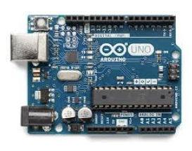
- Arduino microprocessor - Enables to control the electrical circuits logically. Arduino possesses the main component of an integrated circuit chip that can be programmed using the C++ language.

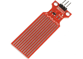
- Water Level Sensor - The water Sensor module is easy to use, compact and lightweight, detects even little moisture, droplets identification and detection sensor. The principle is to measure the size of the trace amount of water droplets through the line with a series of exposed parallel wires.

- Roinco DC Water Pump - A simple aquarium-style pump that uses a centrifugal fan to pull in water and push it up a tube, similar to a propeller in air. These have ratings as to how far they can pump water because if too much pressure is applied, the water will simply come to a standstill or even backwash.
- Other components

| Water Sensor Module components
Our water sensor module consists of 4 main components:
1. Water Sensor module which mainly has 3 pins(+, -, S)
- The ‘+ pin’ is connected to VCC (5v pin port of Arduino)
- The ‘- pin’ is connected to ground (GND) port of Arduino
- The ‘s pin’ is an analogue pin that sends analogue value which can be connected to any analogue ports in Arduino (currently we are using the A0 port).
2. Arduino Board
We are using 4 ports in the Arduino board: VCC(5v), GND, A0(analogue port), and 7(digital port).
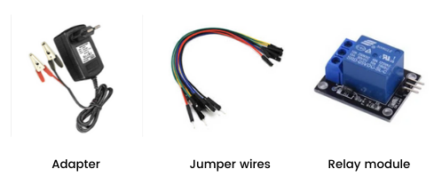
3. Relay SL-C
In the relay, we are using the ground and VCC pins to connect to Arduino. Along with this, we are using the signal port to send signals (pin 7). The relay acts as an electronic switch with 0 as OFF and 1 as ON. There are also NO(Normally Open), NC(Normally Closed), and C(Common Terminal) switches. Here we are using the NO and C ports for our module. We are using the NO switch rather than the NC switch since we want the motor to be operating when the signal is 1. NO switch closes the circuit when the signal is 1.
- NO is connected to the positive terminal of the water pump
- C is connected to the positive terminal of the 12V power source
4. Water Pump
The water pump supplies water whenever it is needed. The positive terminal of the water pump is connected to the NO(normally open) pin of the relay and negative terminal to the 12v power source.
| Code Snippet
| How does it work?
- Water sensor’s analogue pin gives an analogue value that approximately ranges from 0 to 1000 according to the water level (value increases as the water level increases).
- Our first aim was to decide a threshold for this range so that we can start and stop the motor accordingly i.e. the motor will fail to run when the value given out by the sensor is less than the threshold.
- To apply this logic we are using an Arduino which decides when to start and stop the motor. The code snippet for this is given below.
- We are using a relay to turn the motor on and off. When the value given by the sensor is less than the threshold we send a positive signal (1) to the relay, which turns on the motor and turns the motor off after it crosses the threshold which is also managed by the Arduino.
| Benefits
- Reduces water and electricity wastage exponentially - Living in an age where we need to be more conscious of the energy that we use, a water level controller is ideal at saving power. Normally, regulating water levels results in high wastage of electricity and water. However, with automatic controllers, the electricity usage is limited as well as less water is needed to regulate the supply.
- Automatically detects the water levels. Requires zero manual intervention - Another notable advantage with these devices is that they regulate on their own. Eliminating manually operating and monitoring water tanks with a timer switch. The water level is maintained thanks to the automatic operations of these devices.
- Saves money - A water level controller helps save money by limiting excessive water and electricity consumption. These devices accurately regulate how much energy is used to prevent unnecessary water/electricity usage. Hence money saved is quite substantial.
- Multiple applications - households, industrial, agricultural, and more.
- Avoids malfunctions compared to the manual systems.
| The Iot Team
- Abhishek Lal
- Abhishek Mazumdar
- Vrushali Bhosale
- Meena Bisht
- Sumit Madan

.avif)